OpenHome Foundation · Open-source hardware
Sliding Window Opener
A belt-driven retrofit that motorises a sealed sliding window — no track access, nothing structural, still opens by hand if the power's off.
Designed by Pawin Jirasuntornsiri · Firmware MIT · Hardware CC BY 4.0
Status: working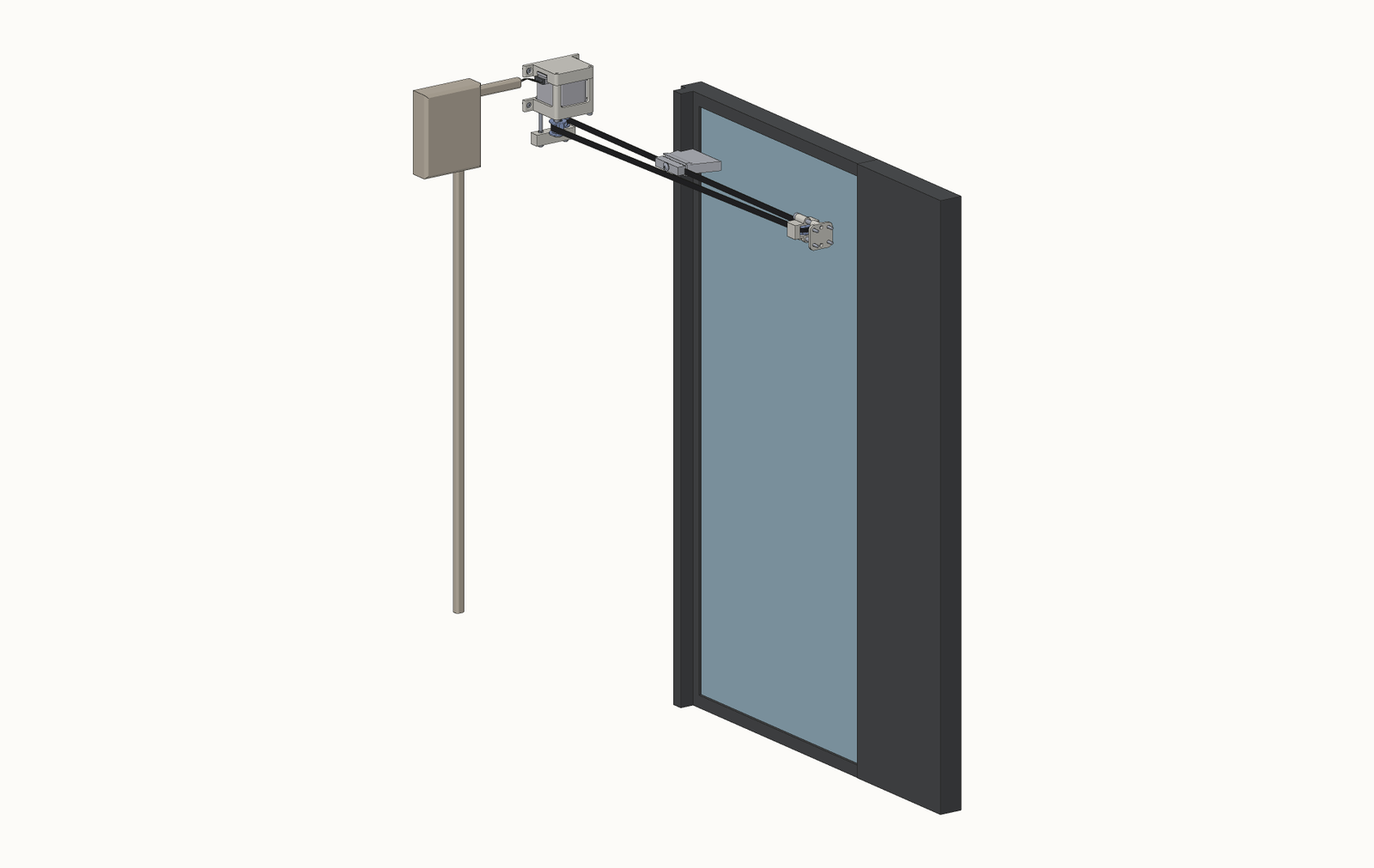
Retrofit, not a replacement
Nothing structural changes
The panel it was built for slides horizontally, hangs entirely from a sealed ceiling track with no access to the carriage inside, and has no bottom track or guide. That constraint shaped the whole design: nothing can be added inside the track, so all the hardware hangs off the jambs at either end and the panel is pulled by a GT2 belt clamped to its vertical stile.
The sealed track stays sealed, the panel is never removed or modified, the glass is not touched, and no part of the window is cut, drilled or replaced. The entire intervention is two brackets on the jambs and a clamp on the panel's stile. Both brackets can be bonded with VHB tape rather than screwed, if you'd rather not drill at all.
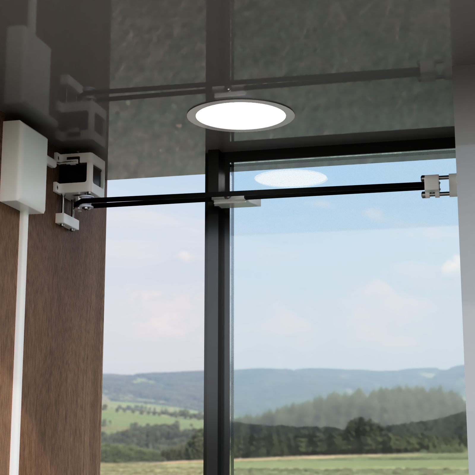
It also stays a normal window. The driver is left disabled when idle, so the panel still slides by hand with the same effort as before — assist mode picks up the nudge and takes over. Nothing is captive, nothing is geared, and there is no clutch to disengage. Take it all off again and you're left with an ordinary sliding window, which is rather the point: this is a weekend addition to a window you already have, not a renovation.
How it works
Belt, two idlers, and a clamp
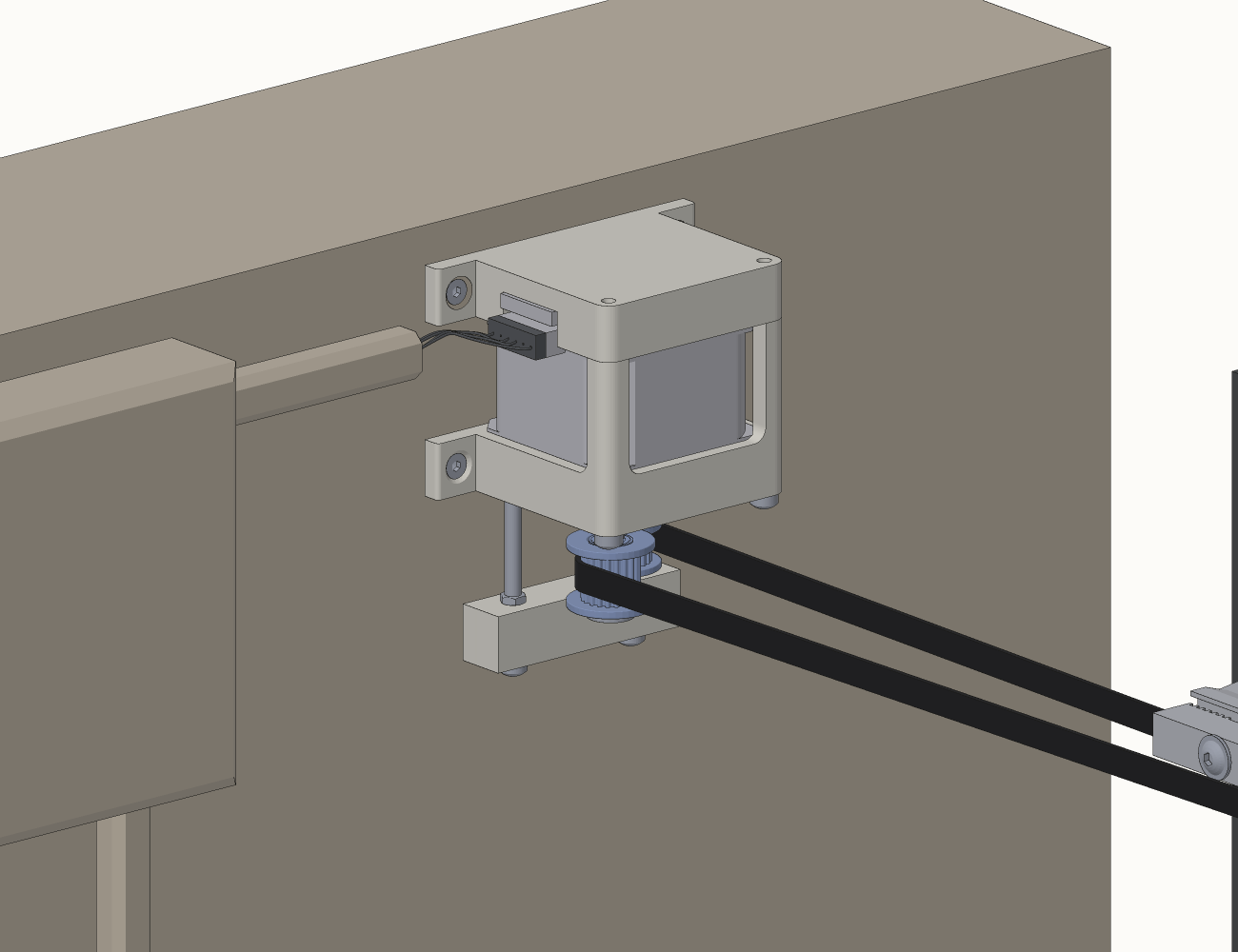
The motor mounts vertically to one jamb with its shaft pointing down. A 20T drive pulley sits under the housing; a 16T guide idler and a 20T tensioning idler set the belt path. At the far end, a printed bracket carries a 20T idler on a sliding carrier that provides the main tension adjustment.
The belt is a single open length. Both cut ends terminate in an aluminium GT2 clamp bolted to the panel's stile, so the clamp both joins the belt and is the thing that gets dragged. The loop lies in a horizontal plane with the belt's 6 mm width vertical, which keeps the whole mechanism inside a shallow band just above the panel.
Auto-calibration
Total travel is not hardcoded. On boot the device seeks the closed limit, backs off until the switch releases, creeps back on slowly and zeroes there, then repeats the same two-stage approach at the open end while counting steps. This sidesteps the microstepping question entirely — whatever mode the driver comes up in, the measured count is correct in those units.
The two-stage approach matters: a single fast pass bounces off the end stop, so splitting it into a fast approach, a backoff, then a slow creep at 200 steps/s means the panel is barely moving at contact — it stops on the switch instead of overshooting, and the trigger point becomes repeatable since it no longer depends on arrival momentum.
Drift correction
On every normal arrival at the open limit, actual position is compared against stored travel. Under 10% difference, the stored value is silently updated; over 10%, it logs a warning and leaves it alone. Belt skips therefore heal themselves on the next full traverse.
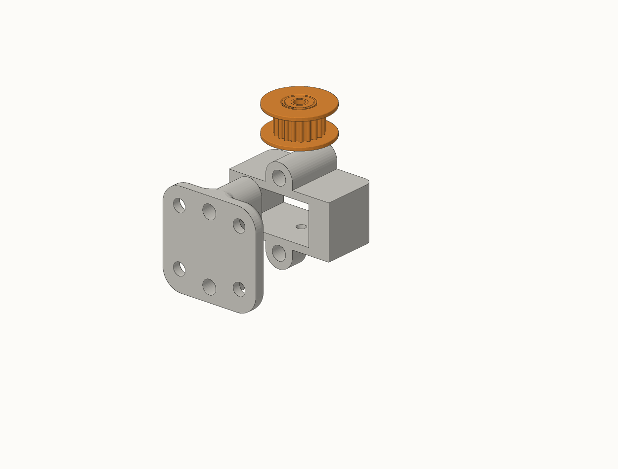
The tensioning idler at the motor end is not part of building the motor unit — it exists purely to take up belt tension, so it's the very last thing that goes on, after the brackets are mounted, the belt is routed, and the clamp is bolted to the panel. It appears in the motor sequence below only so you can see where it lands.
Bill of materials
What you need
Electronics
| Item | Detail |
|---|---|
| MCU | ESP32 DevKit, 30-pin (Node32s), micro-USB |
| Stepper driver | BIGTREETECH TMC2209 v1.3 (110 mΩ RSENSE) |
| Motor | NEMA17 42BYGH40 |
| PSU | 24 V 2 A, 48 W |
| Buck converter | LM2596 adjustable, set to 5.0 V |
| Bulk capacitor | 2200 µF 35 V across driver VS/GND |
| Limit switches | 2× MC-38 reed sensors, enclosed type, tape-mounted |
| Magnet | 1× MC-38 companion magnet, on the stile |
| Perfboard | 7 × 9 cm, point-to-point soldered |
Mechanical
| Item | Detail | Qty |
|---|---|---|
| Drive pulley | GT2 20T, 5 mm bore | 1 |
| Guide idler | GT2 16T W6, 3 mm bore, with bearings | 1 |
| Tensioning idler | GT2 20T, 3 mm bore, with bearings — belt tension only | 1 |
| Far-end idler | GT2 20T W6, 3 mm bore, with bearings | 1 |
| Belt | GT2 6 mm carbon-reinforced, open length | ~2.5× window width |
| Belt clamp | GT2 aluminium timing belt clamp (printable, aluminium preferred) | 1 |
| Tensioner screw | M3, through the 3 mm bore bearing | 1 |
| Idler axle | M2.5 × 16 | 1 |
| Machine screws | M3, assorted lengths, plus nuts and washers | ~14 |
| Heat-set inserts | M3 | 3 |
| Wall fixings | suit your wall, 4 per bracket | 8 |
The STEP files were exported with placeholder fasteners from the CAD library, so they read as 6-32, 10-24, M2.5 and M5 in the geometry. Everything is actually M3, except the M2.5 far-end idler axle. The tensioning idler is an M3 screw through a 3 mm bore bearing — it is not an M5, whatever the STEP says.
Printed parts
| Part | Envelope | Notes |
|---|---|---|
| Motor housing, main body | 45 × 68 × 37 mm | carries the motor and both idlers |
| Motor housing, cover | 45 × 68 × 12 mm | closes the top |
| VHB standoff block | 11 × 48 × 12 mm | flat face for VHB mounting |
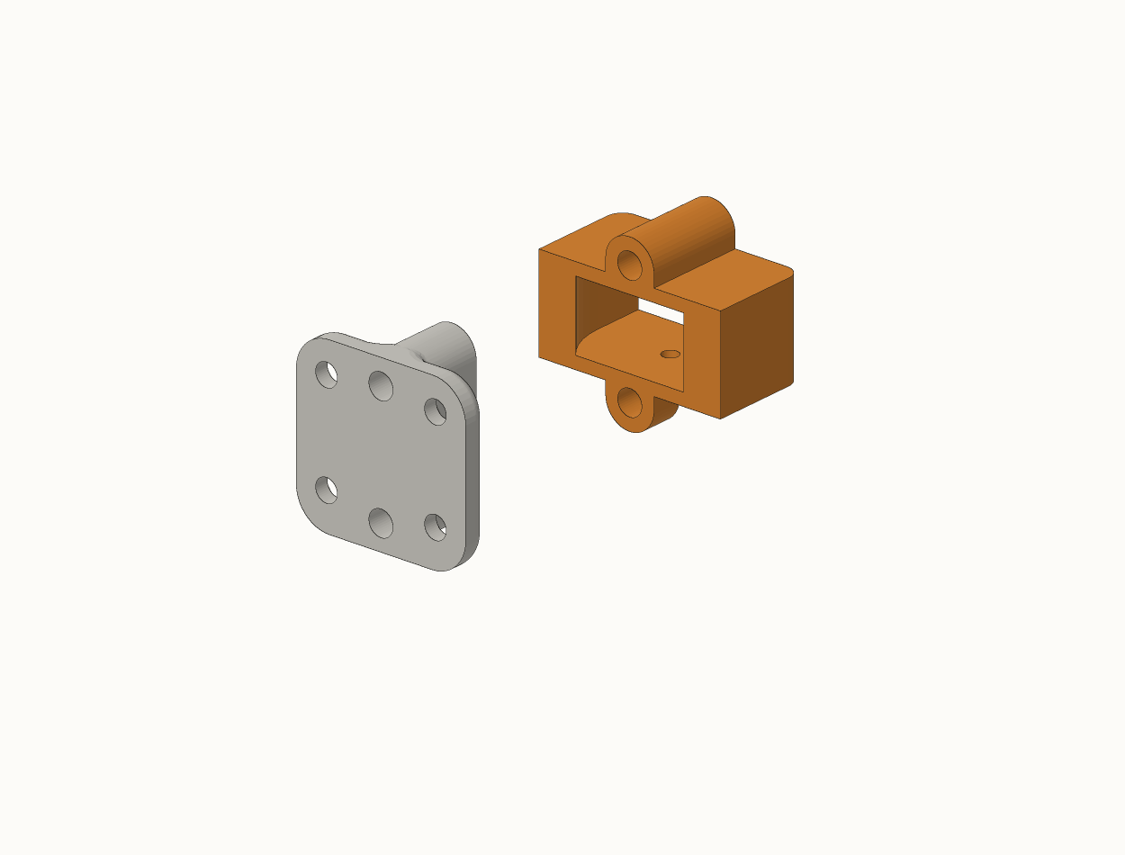
| Idler carrier | 16 × 30 × 27 mm | slides to tension the belt |
| Idler base plate | 14 × 29 × 29 mm | 2× M3 heat-set inserts |
PA6 if you're screwing the brackets to the wall — printed at a 70 °C chamber temperature with no warping. ABS or PETG is fine if you're mounting with VHB tape instead, since the load path is then adhesive rather than a screw pulling through the part. The VHB standoff block exists specifically so tape has a flat, properly sized face to bond to — without it, screws are sufficient but VHB is not.
Wiring
Four sub-circuits
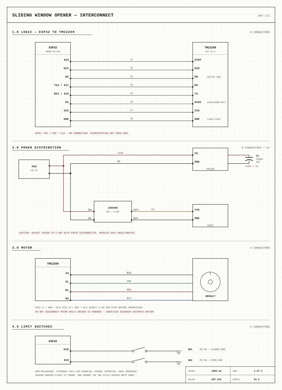
Logic (ESP32 ↔ TMC2209 over UART), power distribution (PSU → driver and buck → ESP32), the motor coils, and the two limit switches.
| From | To |
|---|---|
| ESP32 TX2 (GPIO17) | TMC2209 RX |
| ESP32 RX2 (GPIO16) | TMC2209 TX |
| ESP32 D22 (GPIO22) | TMC2209 STEP |
| ESP32 D23 (GPIO23) | TMC2209 DIR |
| ESP32 D5 (GPIO5) | TMC2209 EN (active LOW) |
| ESP32 D4 (GPIO4) | TMC2209 DIAG (StallGuard) |
| ESP32 3V3 / GND | TMC2209 VIO / GND (the one beside VIO) |
| ESP32 D18 (GPIO18) | MC-38 #1, closed end |
| ESP32 D19 (GPIO19) | MC-38 #2, open end |
| PSU +24 V / − | TMC2209 VS / GND (the one beside VS) |
| 2200 µF cap | across VS / GND |
| Buck OUT+ / OUT− | ESP32 VIN / GND |
| Motor | green → A1, black → A2, red → B1, blue → B2 |
Coil A = green + black, coil B = red + blue; verify ~1–5 Ω per pair. MS1, MS2 and CLK are deliberately left unconnected — on the v1.3 board RX and TX are broken out separately, so no external 1 kΩ resistor is needed. All connections are hardwired.
Driver current. The BTT TMC2209 v1.3 uses 110 mΩ RSENSE. Vref is set to 1.27 V, about 1.4 A RMS. Turning the pot clockwise reduces current.
Inductive kickback destroys TMC drivers, and this is the single most common way they die.
Assembly
Three sub-assemblies
Build the motor housing, the idler carrier, and the belt clamp separately, then install brackets, route the belt, and fit the tensioning idler last (see How it works).
Motor housing
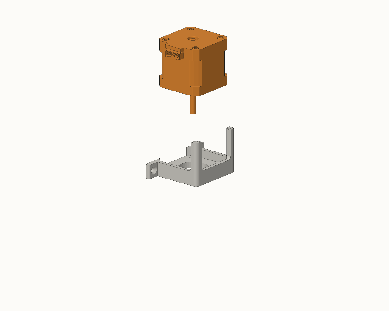
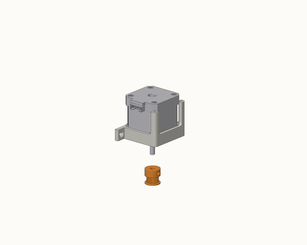
10 steps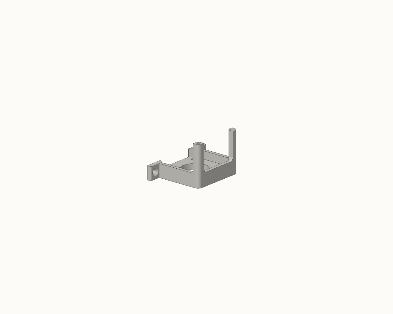
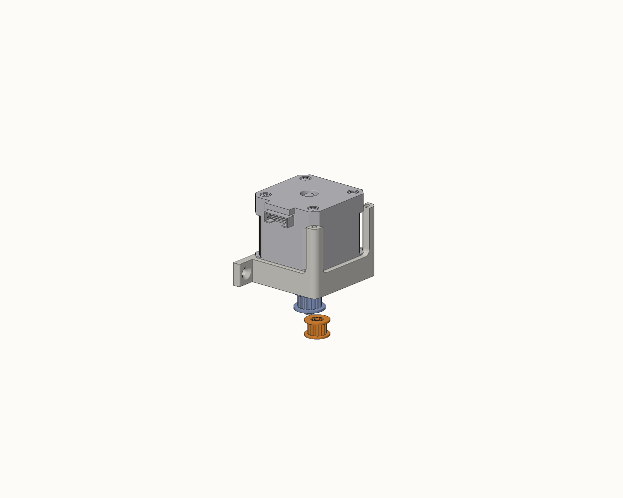
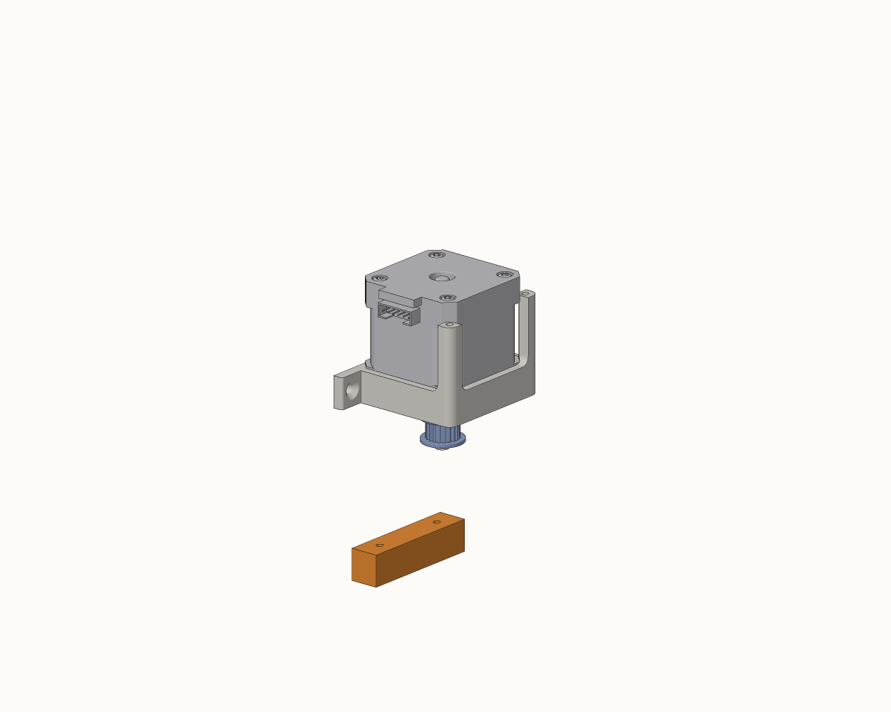
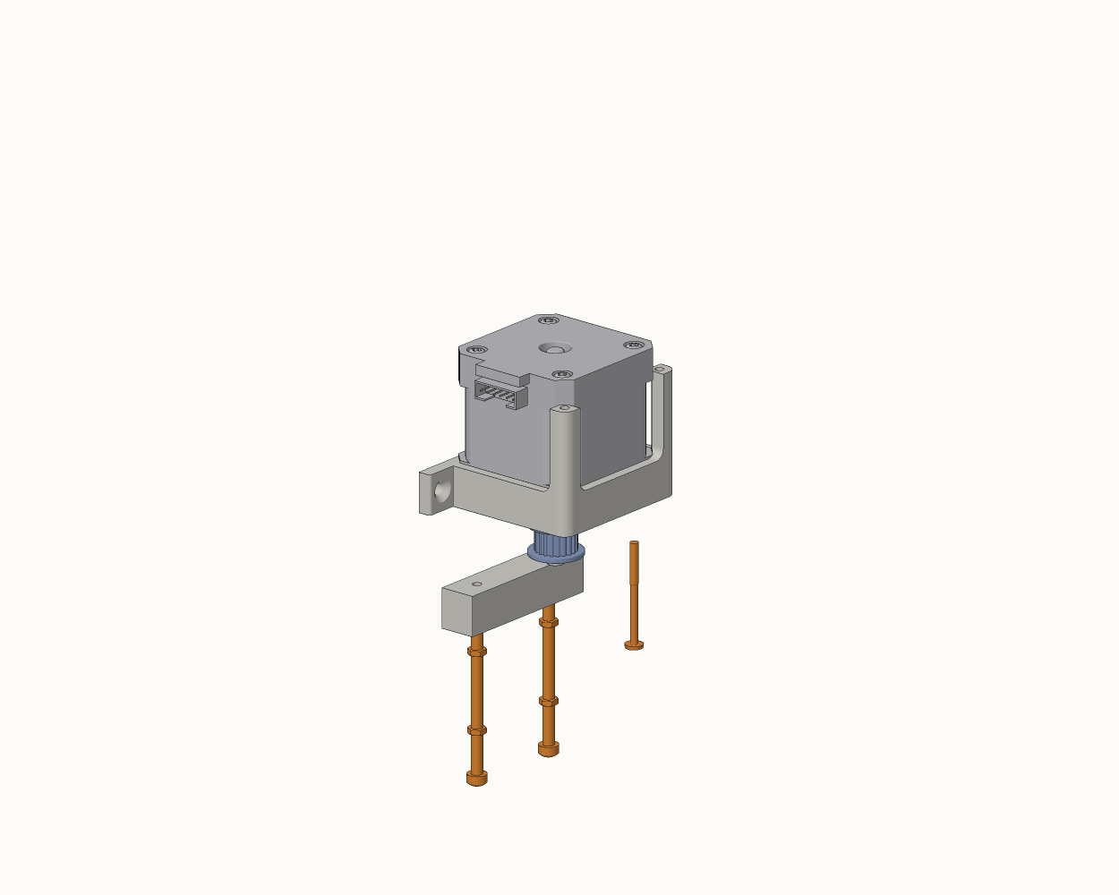
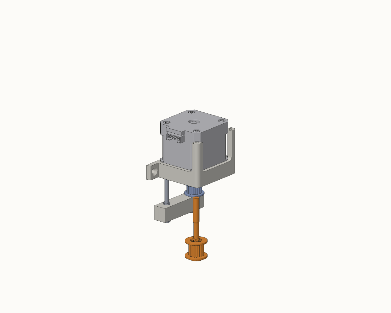
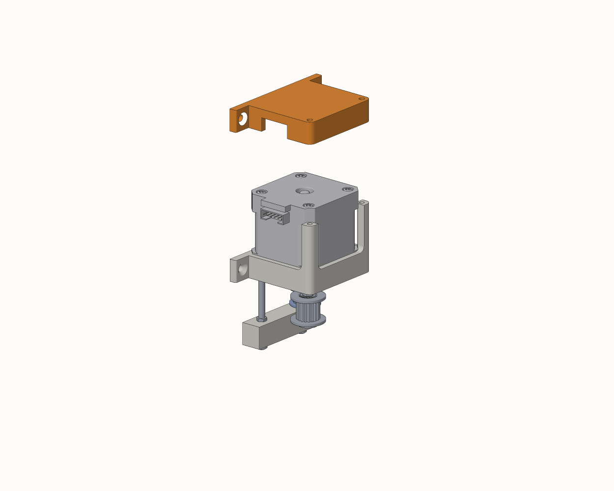
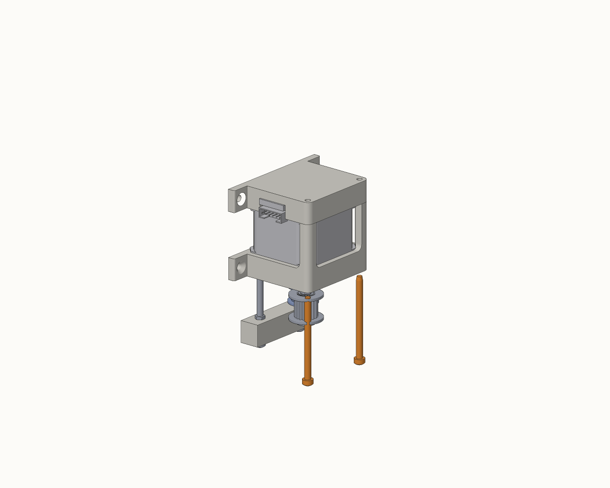
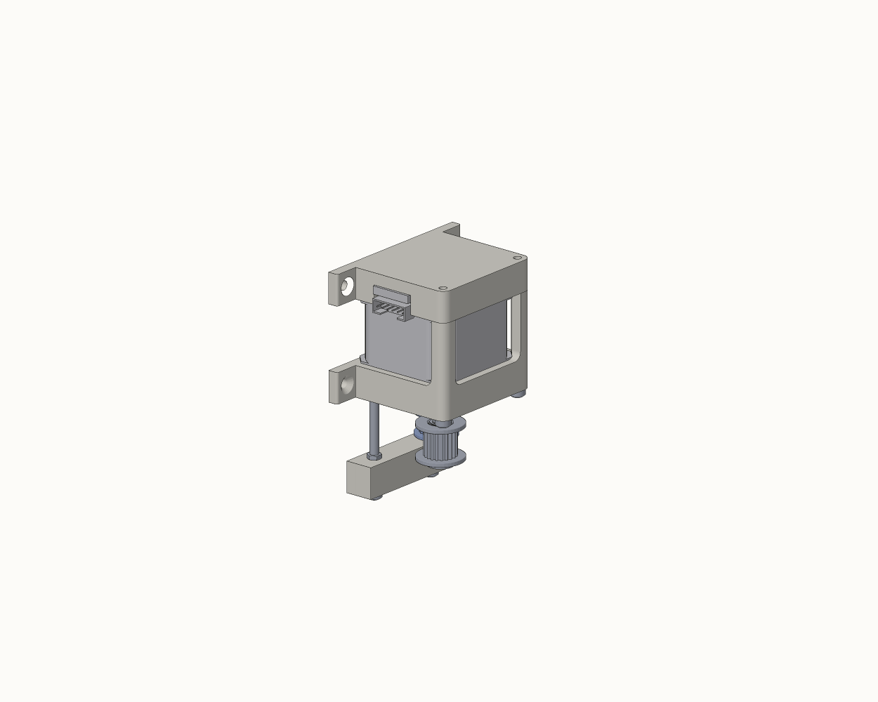
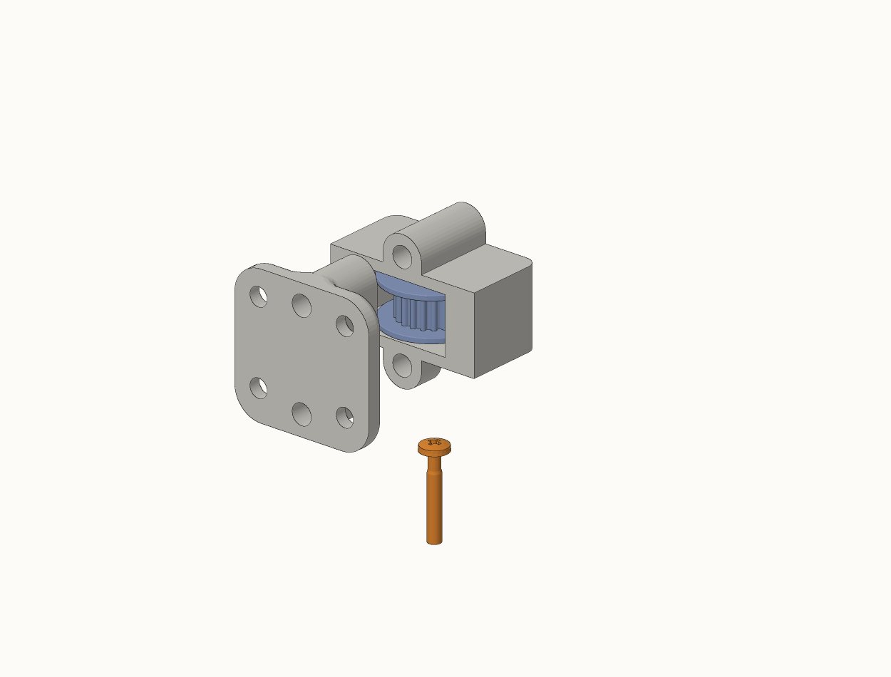
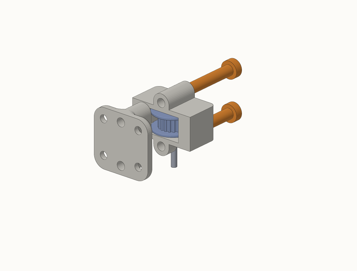
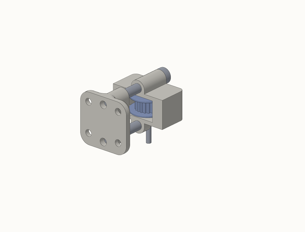
*Fitted here so you can see where it lands — actually the last thing installed. See Fit the tensioning idler last. Shown as M5 in the CAD; it's an M3 through a 3 mm bore bearing.
Idler carrier
6 steps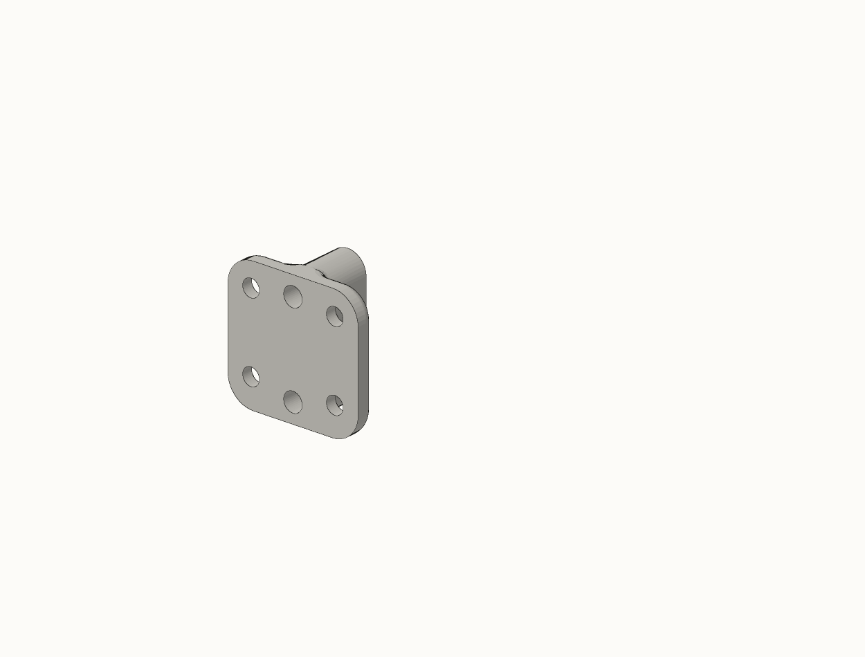
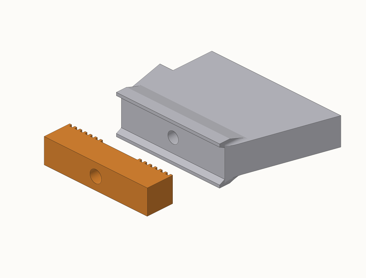
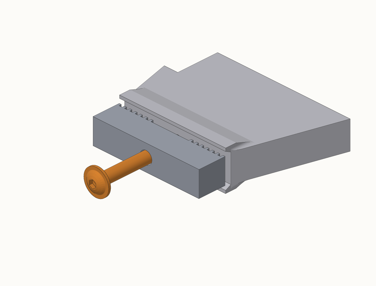
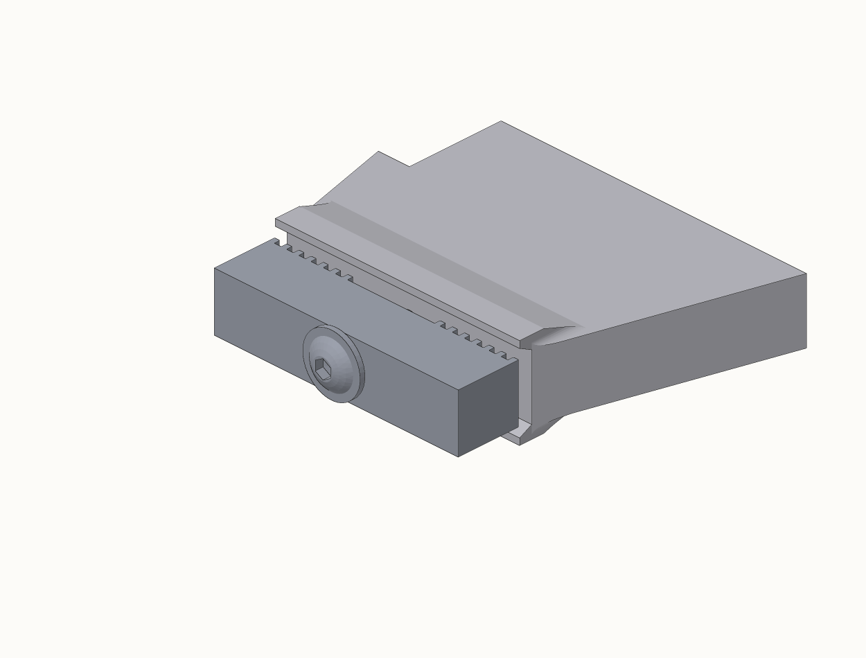
Belt clamp
4 steps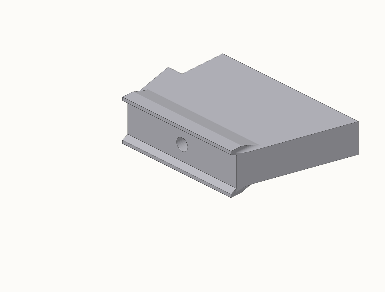
- The idler axle screw is modelled head-up in
Pully Holder.step. It goes in from below — fit it head-down regardless of what the file shows. - The 16T idler and the M5 tensioner are unplaced in
MotorHolder.stepwhen opened on its own. UseAssembly.stepas the reference for their positions.
Installation
Onto the window
With the three sub-assemblies built, this is where the mechanism actually goes onto the wall and the window. Motor unit on one jamb, idler bracket on the other, belt clamp on the panel's leading stile.
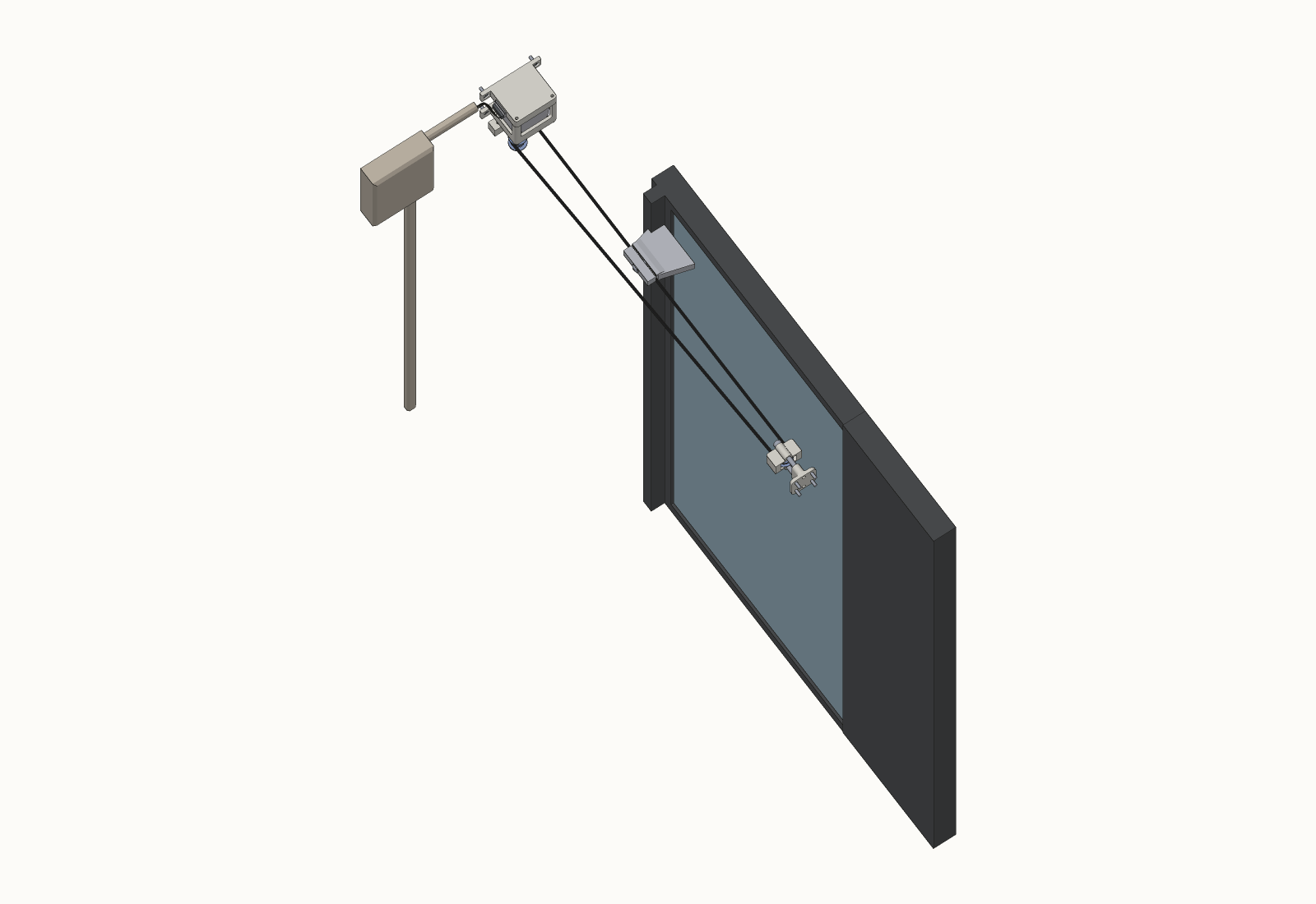
Mounting
Both ends screw to the jambs with 4× M3 countersunk screws each, or bond with VHB using the standoff block. Fix the motor end first, then stretch the belt across and position the idler bracket so the carrier still has adjustment left in both directions.
Belt routing and length
Cut roughly 2.5× the window width. The belt leaves the drive pulley, runs the length of the opening, wraps the far idler, and comes back. Both cut ends go into the aluminium clamp, teeth meshed, and the clamp bolts to the panel stile.
Tensioning
Target 20–30 N. In practice: plucked, the belt should give a dull thud rather than a ring, and mid-span it should deflect 5–10 mm under light finger pressure. Adjust with the two M3 screws on the idler carrier. If that's not enough range, fit the tensioning idler at the motor end (motor unit step 7, "fit last" — see Assembly) and take up the rest there.
A new belt beds in and drops tension, and low tension is the main cause of skipped teeth.
Limit switches
Two MC-38 enclosed reed switches, tape-mounted, one near each end of travel. A single magnet on the stile triggers both. Full positioning procedure in Commissioning below.
The drive pulley has to go on the shaft before the cover, and the grub screws have to be tightened before the housing closes. Get this wrong and it comes apart again.
Commissioning
Power up and calibrate
Set the buck converter output to 5.0 V before connecting the ESP32 — LM2596 modules ship at arbitrary voltages, frequently well above 5 V. Set Vref on the driver, flash the firmware, then power up. The device homes and calibrates itself, so the order beyond that doesn't matter much.
If it runs the wrong way, flip the Reverse direction switch in Home Assistant. It inverts the sign used throughout and triggers a recalibration, so nothing downstream needs changing.
Limit switches
Two MC-38 enclosed reed switches, tape-mounted, one near each end of travel, with a single magnet on the stile triggering both.
Tape them on loosely, slide the panel by hand and watch the binary sensors in Home Assistant until each trips reliably a little before its hard stop. Then run a calibration and confirm the panel stops clean at both ends. Tape is deliberate — it means you can move one a centimetre and try again, which is far faster than trying to get it right on paper.
Whatever offset you land on, the magnet must fully release the switch within backoff_steps
(currently 1200) or the slow confirming pass never re-triggers and homing stalls.
Tuning
| Parameter | Value | Notes |
|---|---|---|
run_speed | 2500 | exposed as a Home Assistant slider |
home_speed | 1000 | fast homing pass |
creep_speed | 200 | slow confirming pass |
backoff_steps | 1200 | must exceed magnet/sensor hysteresis |
accel / decel | 1500 | exposed as a slider |
Home Assistant entities
cover.window with open / close / stop / position. Sliders for run speed and acceleration.
Switches for obstruction stop, assist mode and direction reversal. Buttons to recalibrate and re-home.
Diagnostics for position, measured travel and WiFi signal.
Known issues
What's not finished
DIAG is wired to GPIO4 and read as a plain binary sensor, and the handler stops the motor when it
asserts, but SGTHRS has never been written, so it won't fire meaningfully. A
uart: block exists (id tmc_uart, GPIO17/16, 115200) and is currently unused —
it was added for exactly this. TCOOLTHRS needs to bracket the actual run speed, since
StallGuard is unreliable at very low and very high speeds. Until this works there is no mid-travel
obstruction protection at all, and the panel is heavy glass travelling past a windowsill.
- Belt skipping at higher speed. Partly tension. Acceleration is also suspected — torque demand peaks at breakaway, which is the start of every move. Both are sliders for live tuning.
- Microstepping mode is unknown. The motor ran about 40 rpm at 750 steps/s, implying roughly 1/8. Auto-calibration makes this moot for correctness, but it matters if absolute millimetres are ever needed.
- Nudge-to-assist is limited. It only fires near the closed end, keying off the MC-38 releasing
while the motor is idle; it can't detect a push mid-travel. The proper fix is polling the TMC2209's
MSCNTregister over UART, which tracks shaft rotation even when the driver is disabled. - Buck converter whine. The LM2596 pulse-skips under light load. Output is a clean 5.0 V and it's expected to be inaudible once enclosed; if not, add a small load resistor on the 5 V rail or more output capacitance.
Gotchas
- A 3 MΩ reading between coil pairs is open, not a short — that's leakage through the driver chip when probing at its pins.
- The bulk capacitor makes VS↔GND beep on a continuity test while it charges. Wait for it to settle before calling it a short.
- ESPHome rejects
initial_valueandrestore_valuetogether on a templatenumber— the compile fails. Values reset on reboot as a result; once settled, promote them intosubstitutions. - The driver must stay disabled when idle (EN high) or the panel resists being pushed by hand, which defeats assist mode. Holding torque also means back-driving dumps energy into the driver.
Ideas not yet pursued
- Weather-triggered auto-close on rain forecast or humidity
- PM2.5-aware opening (relevant in Bangkok)
- A physical button on a spare GPIO as a WiFi-independent fallback
Downloads
Everything, to build your own
3D models 11 files
By parts 10 files
Build instructions 2 files
Designed by Pawin Jirasuntornsiri. Firmware MIT licence, hardware and documentation CC BY 4.0. Share it, remix it, sell it if you like — just say where it came from.