OpenHome Foundation · Open-source hardware
Presence Plate
A desk plate that knows whether your thing is on it.
Designed by Pawin Jirasuntornsiri · Rev A · Firmware MIT · Hardware CC BY-SA 4.0
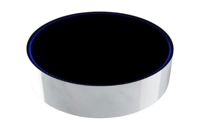
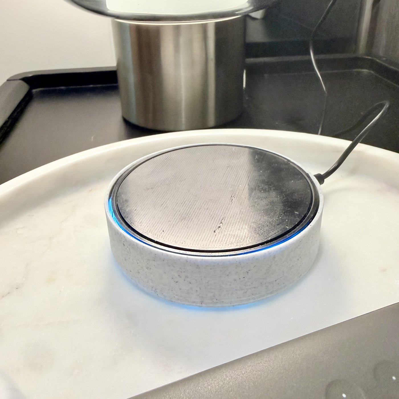
This is the real first prototype
Everything above this line is a CAD render for clarity — this is the actual unit, built from this exact guide, powered on with the ring lit. Top plate is a bare print here, pre-finishing.
How it knows
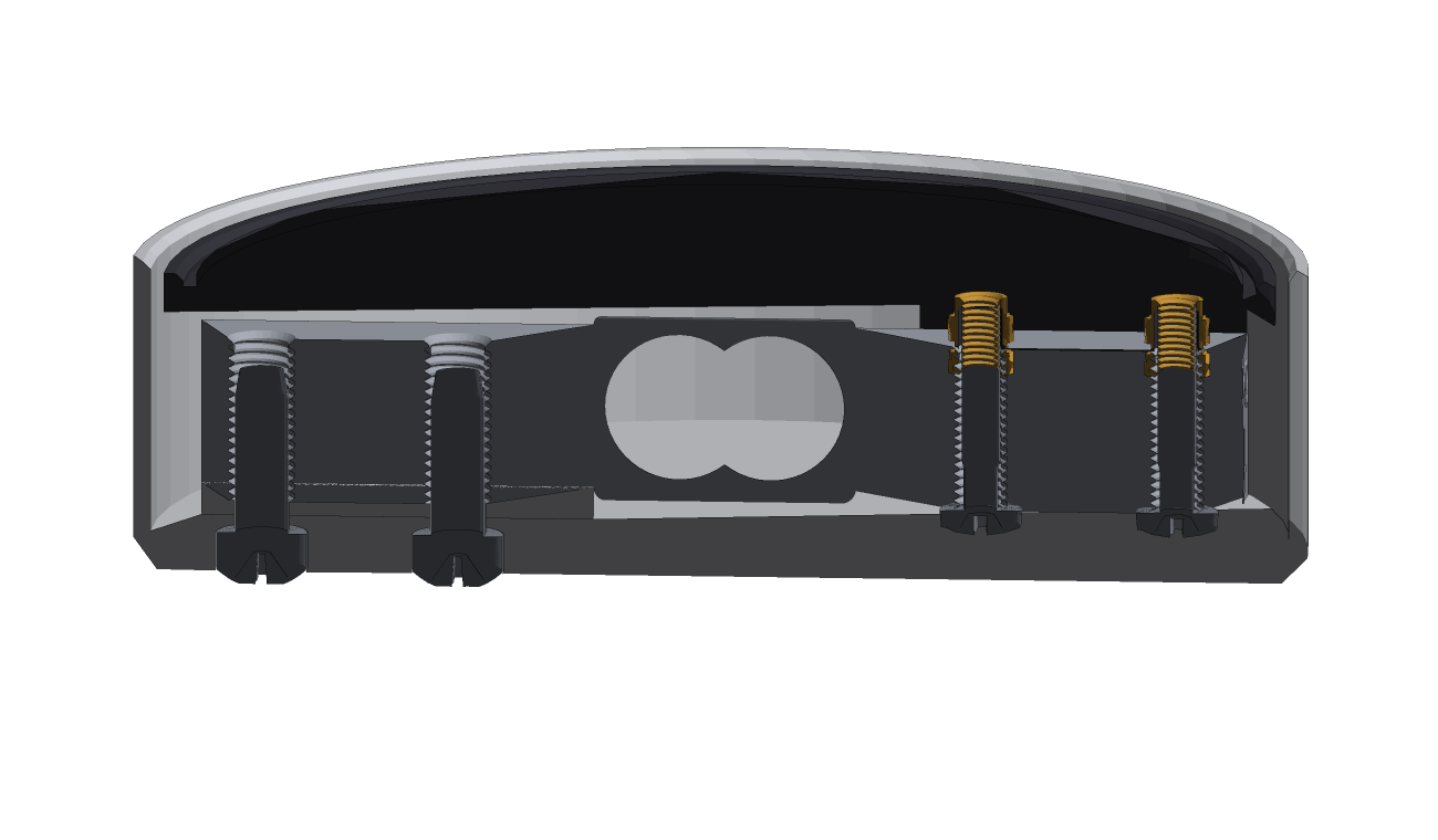
The top plate rests on the free end of a load cell and touches nothing else. Anything put on the plate bends the cell, and the HX711 reads that bend ten times a second.
It does not compare that reading against a fixed threshold. Load cells drift with room temperature, sometimes by more than a small object weighs, so a threshold eventually lies. Instead the firmware watches for the sudden change of something landing or being lifted. Drift is slow. A placement is fast. That is the whole trick.
What's in the box
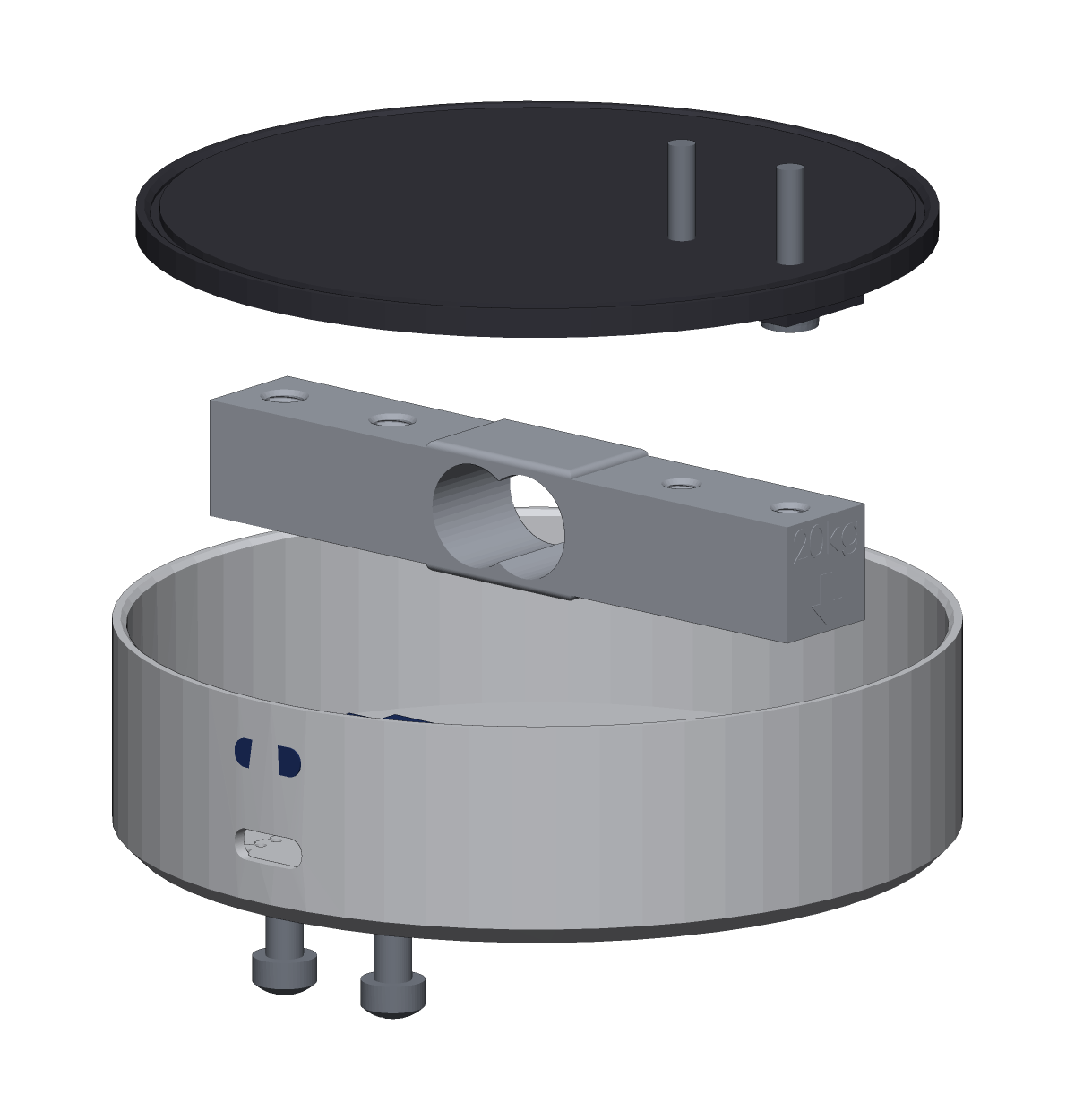
Two printed parts, a load cell, an ESP32-C3, an HX711 and 15 LEDs. Nothing exotic — every part is generic and widely stocked, aside from the load cell and the heat-set inserts, which are worth being fussy about (see Parts).
The build
Nine steps, in order
About 90 minutes plus print time. Do them in order — step 7 is a test that has to happen before the case is closed.
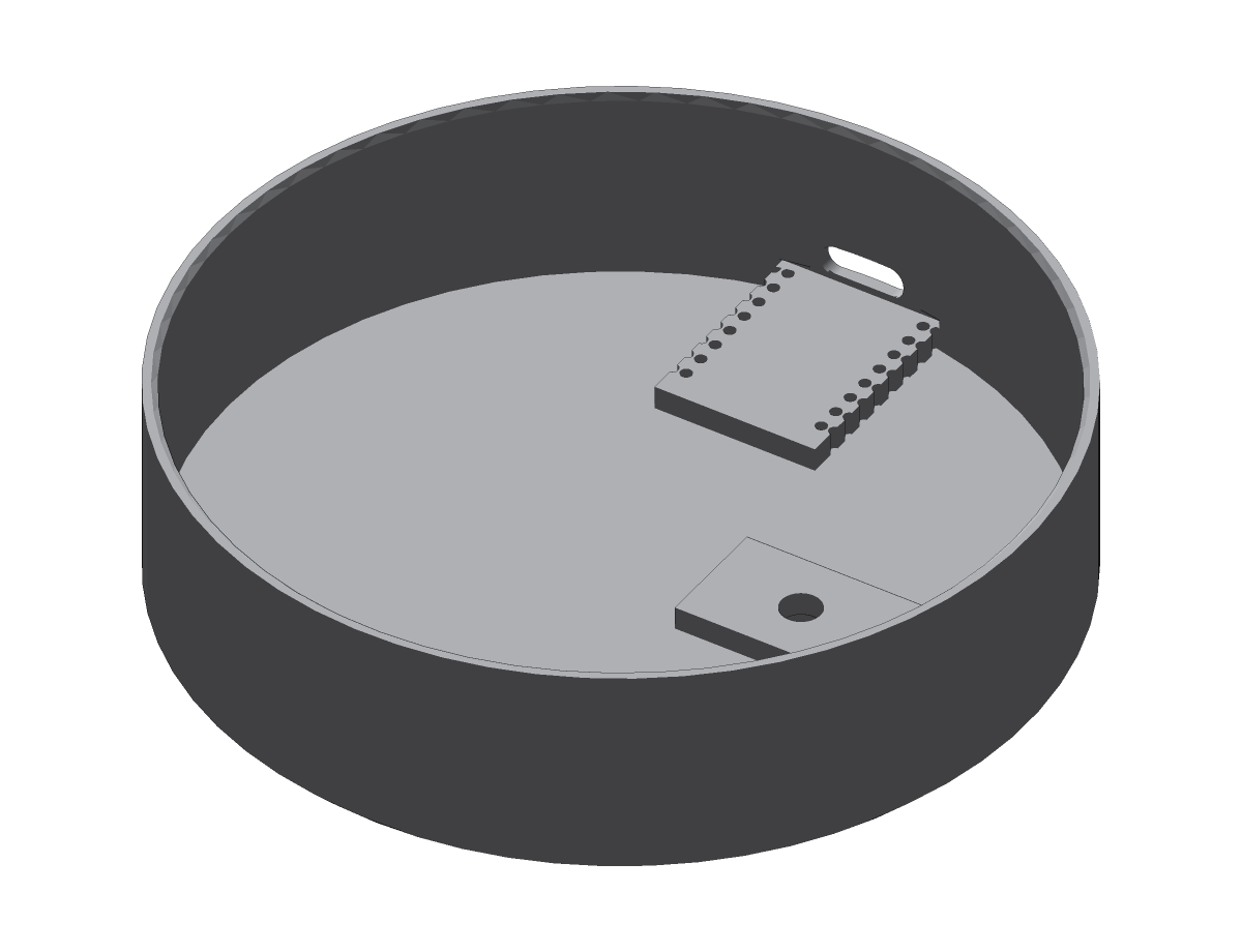
- Line the inside of the case wall with black electrical tape, floor to rim.
- One continuous band. Overlap the ends 10 mm.
- Press flat. No bubbles where the strip will sit.
- Cut the strip to 15 pixels, on a pad line.
- Solder the three wires to the DIN end before fitting.
- Fit the 470 Ω resistor in the data wire, at the strip end.
- Stick the strip around the inside of the wall, over the tape, LEDs facing out.
- Start and finish next to the ESP pocket.
DIN is the end the printed arrows point away from. Wrong end and the strip stays dark.
Keep the strip upright against the wall. Do not curl it flat — that cracks the traces.
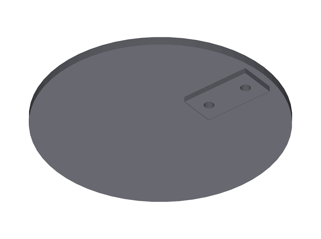
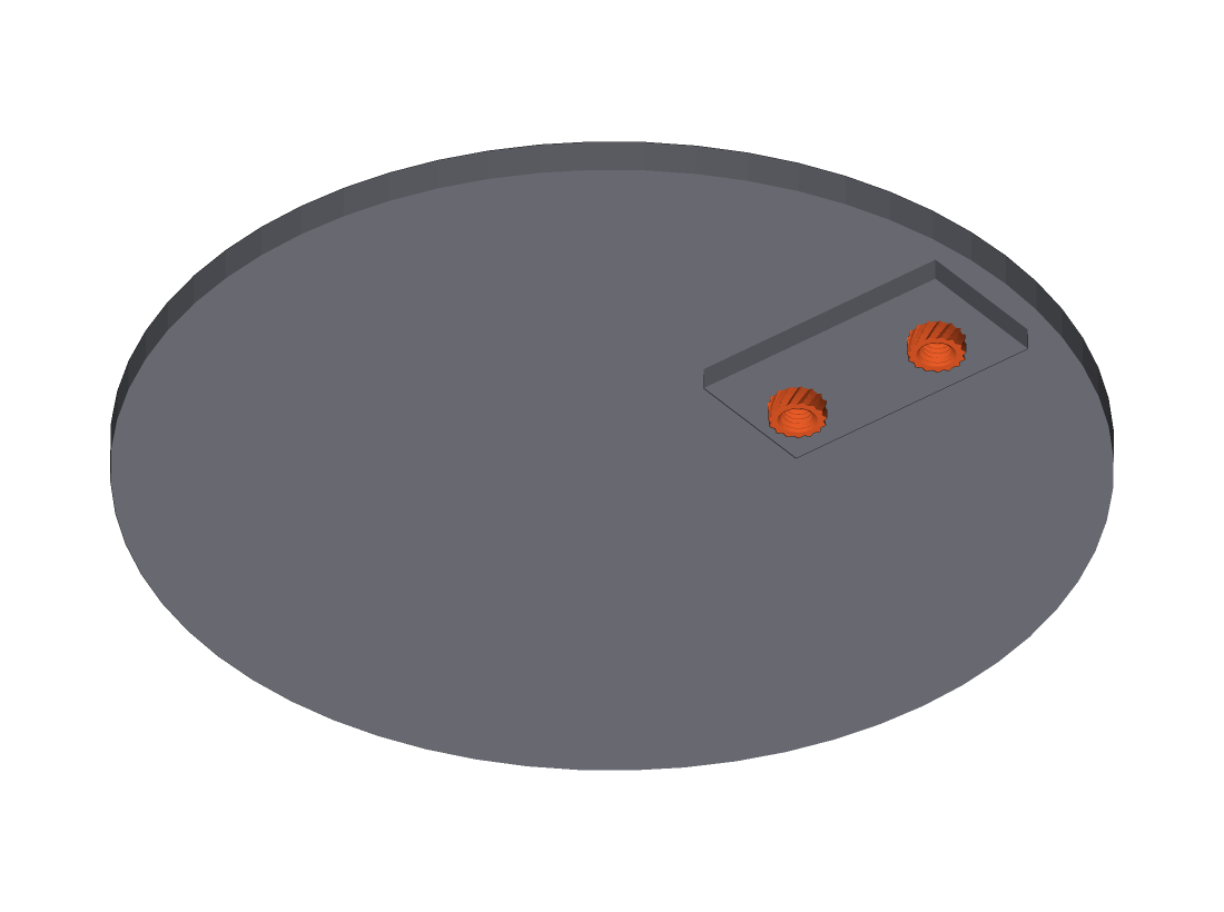
Two holes in the boss on the plate underside. Ø3.5 mm, 3.0 mm deep, 15 mm apart.
- Set the iron to 220 °C for PLA, 240 °C for PETG.
- Sit the insert on the hole.
- Put the iron in it. Let its own weight take it down. Do not push.
- Stop when the flange is flush with the boss face.
- Check flush with a straight edge across the boss while still warm.
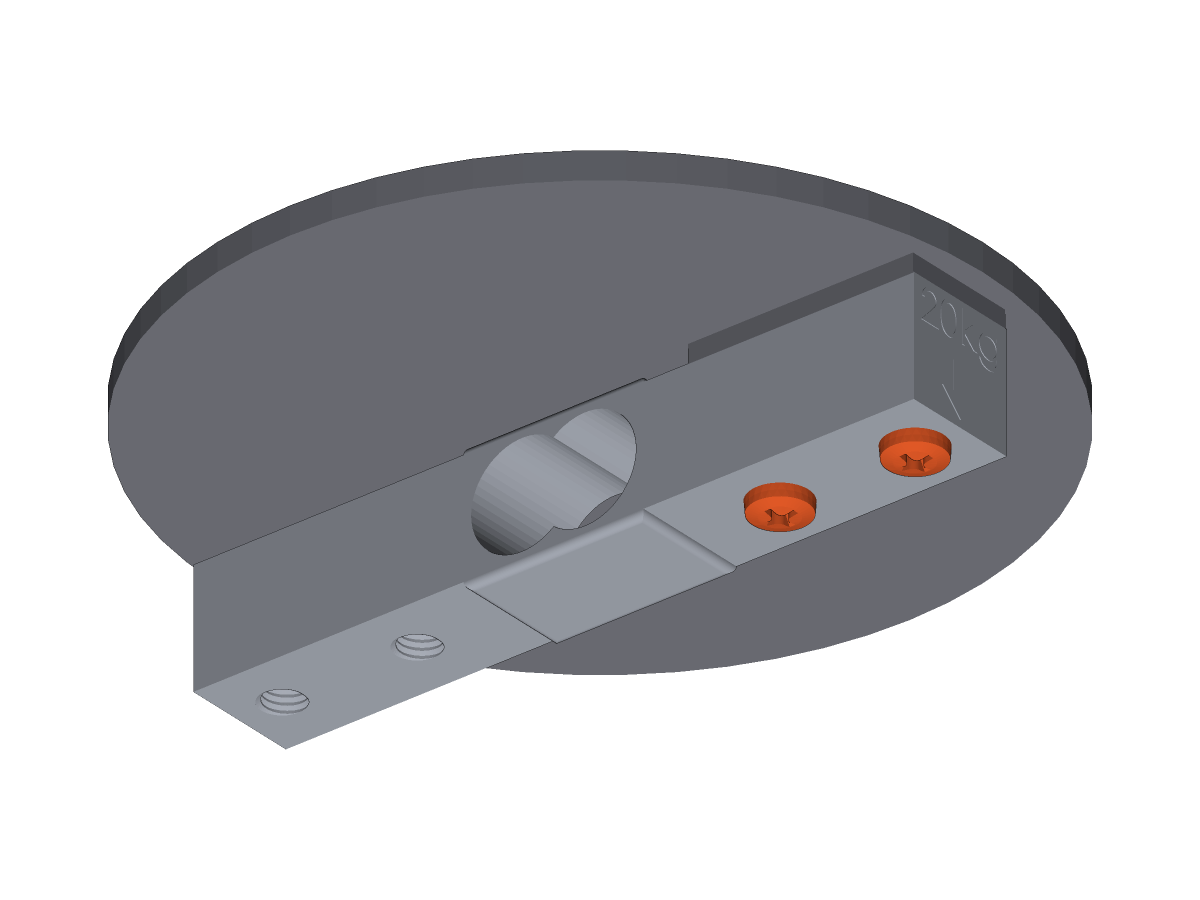
Two M3 × 16 screws, up through the load cell into the inserts.
Marked cells: the arrow points to the free end.
Unmarked: hold one end, press the other. The end that deflects is the free end.
Backwards and the plate reads almost nothing.
- Tighten firm. Do not overtighten — brass in plastic.
- If the cell's holes are M4 or M5, add an M3 washer under each screw head.
- Dry fit the SuperMini in the pocket. Check the USB-C port lines up with the wall slot.
- Superglue at each corner, or a square of VHB.
- Let it set before soldering to it.
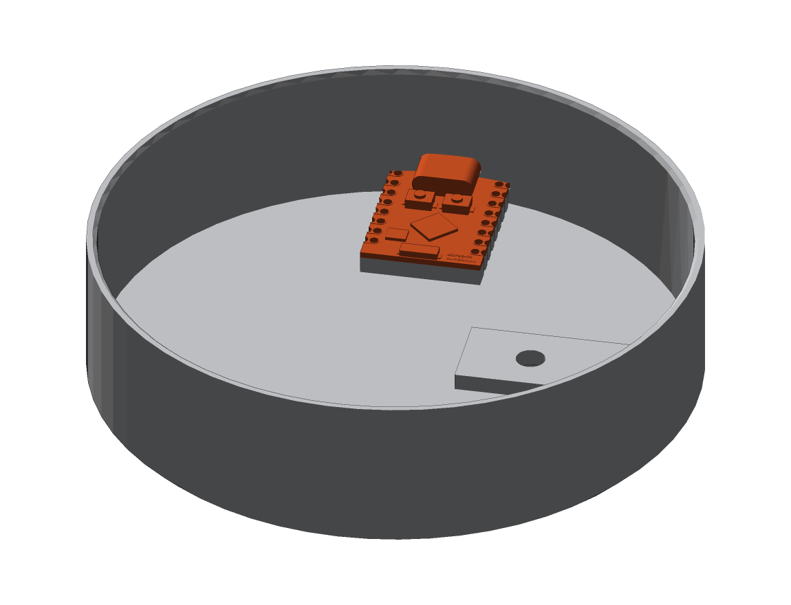
Full diagram and connection table in Wiring below.
- HX711 VCC to 3V3, never 5 V. At 5 V its DOUT drives 5 V into a 3.3 V GPIO.
- Star ground. Every GND wire ends at one physical joint. No daisy chaining.
- 10 µF and 100 nF at the HX711's own pins. Not on the perfboard.
Placement
- HX711 in the empty half of the case, 30–50 mm from the load cell.
- Service loop in the cell's four wires. Anchor them on the fixed end side only.
- Keep the cell wires clear of the strip's power and data. Cross at 90°.
- Nothing may touch the top plate or the free end of the cell.
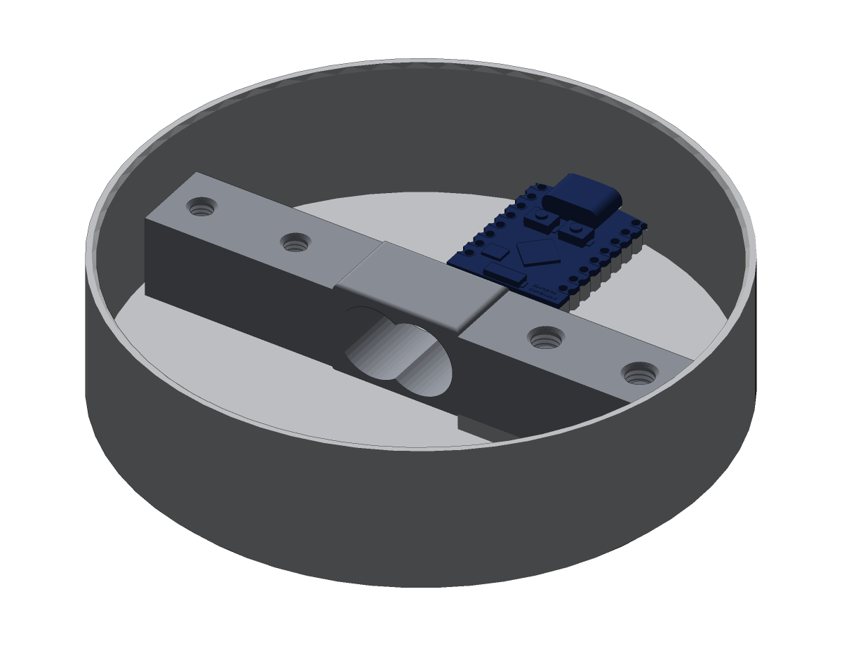
Test with the case open. Everything is reachable now and will not be afterwards.
Put secrets.yaml beside the config:
wifi_ssid: "your-network"
wifi_password: "your-password"
Then:
esphome run presence-plate.yaml
Check in order
- Boots and joins WiFi. Ring runs a slow blue orbit, then one green flash.
- Colours correct. Green flash comes out red → set
rgb_order: RGB, reflash. - Pixel 1 correct. First pixel wrong or flickering, rest fine → fit one 1N4007 in series with the strip's +5 V. Silicon, not Schottky.
- Cell responds. Watch
Load cell raw. Press the plate: the number must move by thousands and return. - Ring goes red, slow orbit. Normal. Means not yet calibrated.
Faults
| Symptom | Cause |
|---|---|
| Load cell raw reads NaN | DT and SCK swapped, or HX711 not powered |
| Load cell raw steady, never changes | Cell not in the load path, or the fixed end was bolted to the plate |
| Load cell raw noisy by thousands at rest | 100 nF not at the HX711 pins, or cell wires running near the strip |
| Board resets when the ring lights | 1000 µF missing or too far from the strip |
| Strip completely dark | DIN connected at the wrong end of the strip |
| First pixel wrong colour, rest fine | 3.3 V data level. Fit a 1N4007 in series with the strip +5 V. |
| Red and green swapped | Set rgb_order: RGB in the config and reflash |
| WiFi drops with 'Auth Expired' | power_save_mode: none and output_power: 15dB missing from the config |
| Plate reads nothing when pressed | Plate is touching the case wall. Sand the plate edge. |
- Two M4 × 16 socket cap screws, up through the counterbores in the underside, into the load cell's fixed end.
- Tighten fully. This joint must not move.
- Fit three silicone feet, evenly spaced.
Gap ≈1 mm, even all the way round.
Press the rim at three points. It must return each time.
Any contact with the wall and the cell reads nothing. Sand the plate edge. Do not loosen anything.
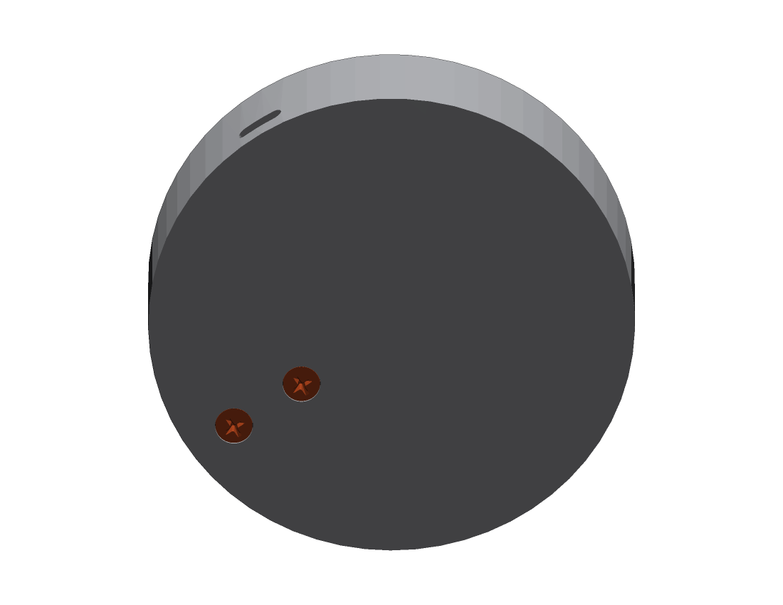
Start it one of two ways:
- Press Calibrate in Home Assistant, or
- Knock
· · — — ·on the plate — short, long, long, short. Tap slowly: 0.5 s, 1 s, 1 s, 0.5 s. The ring fills red. Tap once more to confirm.
Full colour table in Calibration below.
Blue = put it on. Amber = take it off. The Tare button is not needed.
Wiring
One diagram, one table
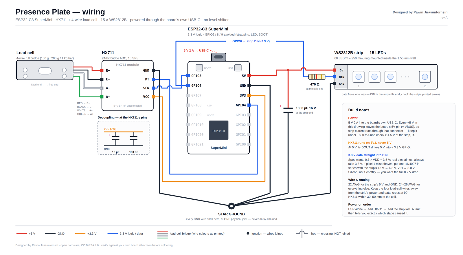
| Group | From | To | Net |
|---|---|---|---|
| Load cell → HX711 | RED | E+ | load cell bridge |
| Load cell → HX711 | BLACK | E− | load cell bridge |
| Load cell → HX711 | WHITE | A− | load cell bridge |
| Load cell → HX711 | GREEN | A+ | load cell bridge |
| Load cell → HX711 | B+ and B− | not connected | — |
| HX711 → ESP32-C3 | VCC | 3V3 (never 5 V) | +3.3 V |
| HX711 → ESP32-C3 | DT | GPIO4 | 3.3 V logic |
| HX711 → ESP32-C3 | SCK | GPIO5 | 3.3 V logic |
| HX711 → ESP32-C3 | GND | Star ground | GND |
| LED ring | ESP GPIO6 → 470 Ω | Strip DIN | 3.3 V data |
| LED ring | ESP 5V | Strip 5V | +5 V |
| LED ring | Strip GND | Star ground | GND |
| Capacitors | 1000 µF | Across strip 5V / GND, at the strip | +5 V |
| Capacitors | 10 µF + 100 nF | Across HX711 VCC / GND, at the pins | +3.3 V |
- HX711 VCC to 3V3, never 5 V. At 5 V its DOUT drives 5 V into a 3.3 V GPIO.
- Star ground. Every GND wire ends at one physical joint. No daisy chaining.
- 10 µF and 100 nF at the HX711's own pins. Not on the perfboard.
If the LED strip misbehaves
The strip runs on 5 V and wants a data signal of at least 3.5 V. The ESP32-C3 puts out 3.3 V. Most strips accept it. If the first pixel is the wrong colour or flickers while the rest are fine, fit one 1N4007 diode in series with the strip's +5 V. That drops the strip to about 4.3 V and brings the threshold down to 3.0 V. Use a silicon diode, not a Schottky.
Parts
What you need
Everything below is generic and widely available. The only two things worth being fussy about are the load cell and the heat-set inserts.
Plate holes are Ø3.5 × 3.0 mm deep. Use 3 mm inserts.
4 mm inserts bottom out 1 mm proud and stop the load cell seating flat. If you already have 4 mm, drill the holes to 4.5 mm with a 3.5 mm bit first.
The STEP file shows Insert M3 D5 L5mm — a library placeholder. D5 does not fit a Ø3.5 hole.
Count the wires in the listing photo. Four wires is a full bridge and works. Three-wire pads, sold for bathroom-scale repair, are half bridges and will not work.
Printed
| Part | Qty | Spec | Note |
|---|---|---|---|
| Case | 1 | Ø90 × 24 mm | Open side up. No supports. White filament. 3 perimeters. |
| Top plate | 1 | Ø85 × 3 mm, 2 mm boss | Boss down, flat on the bed. Any colour. |
Electronics
| Part | Qty | Spec | Note |
|---|---|---|---|
| ESP32-C3 SuperMini | 1 | — | The pocket is cut for this board |
| HX711 module | 1 | Green breakout | Not in the CAD. Mounts in the empty half. |
| Bar load cell | 1 | 80 mm, 15 mm hole spacing | MUST be 4-wire full bridge. |
| WS2812B strip, 60 LED/m | 15 px | ≈250 mm | |
| 470 Ω resistor | 1 | — | Series with DIN, at the strip end |
| 1000 µF 16 V electrolytic | 1 | — | At the strip's 5 V/GND |
| 10 µF electrolytic | 1 | — | At the HX711 pins |
| 100 nF ceramic | 1 | — | At the HX711 pins |
| 1N4007 diode | 1 | — | Spare. Fit only if pixel 1 misbehaves. |
| 5 V 2 A supply | 1 | ≥2 A on the label | |
| USB-C cable | 1 | DATA capable | Test it on a phone first |
| Hookup wire | — | 22 AWG strip power, 24–26 AWG elsewhere |
Hardware
| Part | Qty | Spec | Note |
|---|---|---|---|
| M3 heat-set insert | 2 | 3 mm long | Top plate. NOT 4 mm — see errata. |
| M3 × 16 screw | 2 | — | Load cell free end → plate |
| M4 × 16 socket cap screw | 2 | — | Base → load cell fixed end |
| Black electrical tape | — | — | Case wall |
| Superglue or VHB tape | — | — | ESP |
| Silicone feet | 3 | — | Underside. Three, not four. |
Tools
| Tool | Qty | Spec |
|---|---|---|
| Soldering iron | 1 | Heat-set tip or conical tip |
| Multimeter | 1 | Continuity and DC volts |
| Hex keys | 1 set | 2 mm, 2.5 mm |
| Flush cutters, wire strippers | 1 set | — |
| 3.5 mm drill bit | 1 | Only if deepening the insert holes |
Printing
- Case: open side up, no supports, white filament, 3 perimeters.
- Top plate: boss side down, flat on the bed so the visible face is the smooth one. Any colour.
- PLA or PETG. Use PETG above 25 °C ambient.
Before you start
- Meter the load cell. Red↔Black ≈ 1 kΩ. White↔Green ≈ 1 kΩ. Every wire to every other: finite, never open.
- Plug the bare ESP into USB. Confirm it enumerates.
- Drop the top plate into the case. It must clear the wall all round.
Firmware
Configure and flash
The device runs ESPHome. All its behaviour is in one text file, presence-plate.yaml.
Four settings at the top are the only ones most people change.
device_name:     "presence-plate" # hostname and entity prefix
object_name:     "object"         # appears in entity names
num_leds:        "15"               # pixels on your ring
cell_rating_g:   "5000"             # the number printed on your load cell
Everything else has a working default.
Flashing
esphome run presence-plate.yaml
First time is over USB. After that it updates over WiFi. You need a secrets.yaml beside
it with wifi_ssid and wifi_password.
Home Assistant entities
binary_sensor.<name>_<object>_on_plate     occupancy — the main one
light.<name>_<object>_ring                 the ring, with effects
sensor.<name>_plate_weight                 grams
sensor.<name>_change_per_window            diagnostic
sensor.<name>_learned_<object>_weight      diagnostic
sensor.<name>_counts_per_gram              diagnostic
sensor.<name>_load_cell_raw                diagnostic
button.<name>_calibrate
Example automation
Glow orange if the object is still sitting there five minutes later, and stop when it is picked up.
automation:
  - alias: "Plate: nag if left behind"
    triggers:
      - trigger: state
        entity_id: binary_sensor.presence_plate_object_on_plate
        to: "on"
        for: "00:05:00"
    actions:
      - action: light.turn_on
        target:
          entity_id: light.presence_plate_object_ring
        data:
          brightness_pct: 60
          rgb_color: [255, 90, 0]
          effect: "Orbit"

  - alias: "Plate: stop nagging once taken"
    triggers:
      - trigger: state
        entity_id: binary_sensor.presence_plate_object_on_plate
        to: "off"
    actions:
      - action: light.turn_off
        target:
          entity_id: light.presence_plate_object_ring
Tuning
| Symptom | Setting | Change to | Note |
|---|---|---|---|
| Placements are missed | step_window_ms | 800–1000 | Watch 'Change per window' while placing. The spike must exceed learned weight × 0.75. |
| False events | step_fraction | 0.9 | |
| Double triggers on one placement | event_lockout_ms | raise | |
| Calibration reads low | cal_settle | raise | Minimum 800 ms |
| Tap rhythm never matches | cell_poll | tap slower, or 15 ms with the 80 SPS mod | 80 SPS mod: cut the trace tying HX711 pin 15 to GND, tie pin 15 to DVDD, halve the four tap windows |
| Weight reads wildly wrong | cell_rating_g | match your cell | Check 'Counts per gram' against the table in the config |
Calibration
The light-colour language
The device learns what your object weighs by watching you put it on three times. Fifteen seconds. The ring tells you what to do at every point, so there is nothing to memorise except two colours.
Blue means put it on. Amber means take it off.
Starting it
- Press Calibrate in Home Assistant, or
- Knock
· · — — ·on the plate — short, long, long, short. Tap slowly: about 0.5 s, 1 s, 1 s, 0.5 s between knocks. The ring fills red. Tap once more while it does to confirm.
Tap deliberately slowly. The sensor is read ten times a second, and a quick tap can land entirely between two readings.
What the ring is telling you
| Ring state | Meaning | Duration |
|---|---|---|
| Amber, filling | Clear the plate | 4 seconds |
| Blue, breathing | Put the object on | Waits up to 45 s |
| Green pixels appear | Sample captured | 5 pixels per sample, 3 samples |
| Amber, breathing | Take the object off | Waits up to 45 s |
| Green flash then orbit | Done | ~15 s total |
| Red flash | Timed out, nothing changed | Start again |
| Red slow orbit at boot | Never calibrated | Runs until calibrated |
| Blue slow orbit at boot | Connecting to WiFi | Up to 120 s |
If it fails
A red flash means it timed out and nothing changed. Run it again. The most common cause is leaving the object on the plate during the first amber countdown, which is the "clear the plate" phase.
You should never need the Tare button. Calibration tares itself against an empty plate every time.
Design notes
Dimensions
All measured from the CAD file. Datum is the underside of the case.
| Feature | Value |
|---|---|
| Overall | Ø90.0 × 24.0 mm |
| Case outer diameter | 90.0 mm |
| Case bore | 86.9 mm |
| Case wall thickness | 1.55 mm |
| Case floor thickness | 3.0 mm |
| Top plate | Ø85.0 × 3.0 mm |
| Top plate boss | +2.0 mm |
| Plate to bore radial gap | 1.0 mm |
| Plate top below the rim | 0.88 mm |
| Plate insert holes | 2 × Ø3.5 mm, 3.0 mm deep |
| Plate insert hole positions | 20 mm and 35 mm from centre |
| Base screw holes | 2 × Ø4.3 mm through |
| Base screw counterbores | Ø7.0 mm × 3.0 mm deep |
| Hole spacing, both ends | 15.0 mm |
| Load cell pad, proud of floor | 2.5 mm |
| ESP pocket | 17.8 × 24.0 mm |
| ESP header holes | 2 × 8 at 2.54 mm pitch |
| Load cell envelope | 80.1 × 12.7 × 14.3 mm |
Choosing a load cell
Drift is about 0.05% of a cell's full scale regardless of what is on the plate, so a 5 kg cell drifts around 2.5 g whether it is weighing 2 g or 2 kg. The step detection makes that survivable, but for objects under about 20 g a 100 g or 200 g cell is worth more than any amount of firmware. The bar in this enclosure is an 80 mm, 15 mm-hole-spacing form factor; 100 g cells exist in the same footprint.
Known issues — Rev A
- Heat-set insert length. The STEP file has a part named
Insert M3 D5 L5mmsitting in the Ø3.5 mm holes — a CAD library placeholder that cannot physically fit. Use 3 mm long inserts. Next revision will raise the plate boss from 2 mm to 4 mm so the hole can be 5 mm deep. - CAD placeholders. The load cell in the STEP file is embossed 20 kg and the base fasteners are modelled as 8-32 UNC tapping screws. Neither is what gets built — build with M4, and whatever cell rating you bought. Do not take dimensions off those two parts.
- Ghost setting in the firmware.
baseline_rate_gappears twice in the tuning comments but isn't read by any code, and the "creep the baseline" behaviour it implies isn't implemented. Ignore both — re-baselining on every event is what actually handles drift.
Fixed since the first draft: the step detector's third if block, which tested an
undeclared variable thr, has been removed; the device name and the entity names in the
comments now match what the file actually ships. The firmware compiles.
Downloads
Everything, to build your own
3D models 4 files
Build instructions 3 files
Designed by Pawin Jirasuntornsiri. Firmware MIT licence, hardware CC BY-SA 4.0. Attribution appreciated, not required.